What is Diesel Engine Fuel Injection Pump ?
Fuel injection pump is the important part of diesel engine. Fuel injection pump assembly is usually composed of fuel injection pump, governor and other components together to form an integral whole. The governor is the guarantee of the low-speed diesel engine operation and the maximum speed limit, ensure that the injection volume and speed to maintain a certain relationship between the parts of. And the fuel injection pump is the most important part of the diesel engine, the diesel engine is considered as the “heart” of components, it once the problem can make the whole diesel engine.
1)Fuel Injection Pump Effect
The timing, quantitative, constant pressure to the fuel injector conveying high-pressure fuel. Get good spraying quality, should be the injection pressure increased to 10-20MPa. In accordance with the provisions of the injection and stop the fuel injection.
2) The Requirement of Fuel Injection Pump
(1) according to the diesel engine sequential fuel, and each cylinder oil supply uniform.
(2) of the cylinder fuel supply advance angle, is not larger than 0.5degree crank angle
(3) of each cylinder injection duration to be equal
(4) hydraulic establishment and oil stop must quickly, preventing leakage phenomenon
3) Fuel Injection Pump Classification
1) of fuel injection pump plunger type: good performance, reliable use, wide application.
2) pump injector type: fuel injection pump and injector are integrated, less high pressure tubing
3) the rotor type injection pump: rely on the rotor rotation to achieve a fuel pump oil and distribution. Small volume, the quality of small, low cost, convenient use and so on.
4) the plunger type fuel injection pump working principle
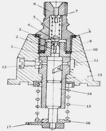
Fuel injection pump assembly: multi cylinder diesel engine, each cylinder needs a set of oil pump body oil, known as the pump, the branch pump assembly in the same housing, sharing a camshaft drive.
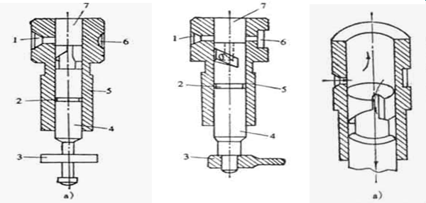
(1)plunger pair structure
The upper part of the plunger piston: smooth cylinder, the upper milling spiral groove or slot and the use of straight groove or hole ( axial and radial hole ) to the upper end of the slot and the plunger pump oil chamber.
Central: plunger oil tank, to keep a small leakage of diesel, lubricating working surface
Plunger lower: installation of spring seat cylinder and the convex block ( or pressure regulating arm )
The plunger sleeve : the inner wall is smooth cylindrical hole, and the outer cylindrical surface of sliding column
The upper part is provided with one oil inlet, oil return with holes. Installed in the casing seat hole, and a positioning hole is fixed by a positioning screw, and the sleeve to rotate.
Material: plunger pair with the wear resistance of high quality alloy steel, to heat and aging treatment.
Note: plunger and sleeve is a pair of precision parts, both to0.001~0.003mm gap and high precision with matching, by grinding, not interchangeable.
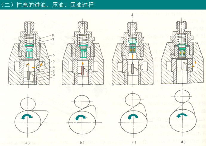
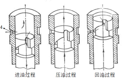
(2) the plunger oil inlet, oil pressure, oil return process
Enter oil: the plunger down – vacuum suction of oil through the oil hole is sucked plunger4, continue to uplink portion of fuel from the pump chamber to the low pressure oil chamber squeeze – to the plunger cylinder oil hole is closed.
Pressure oil: closed oil inlet hole pump oil pressure suddenly increases indoor – and overcoming oil outlet valve spring force open the oil valve, high pressure oil inlet pipe
Return oil: plunger to map C chute is connected with the oil inlet hole on – pump cavity fuel passes through the central hole of plunger – chute – oil hole – return to the low pressure chamber, chamber of the pump oil decreased rapidly, under the action of the spring valve oil return – fuel stop
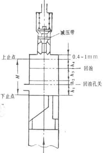
Plunger upward journey: ready to travel, decompression with stroke, effective travel and the remainder stroke.
Prepare to travel from the BDC to plunger oil inlet hole is closed by the end of the moving distance.Decompression with trip oil inlet hole close to the oil valve opening ( decompression with began to leave the seat guide hole) when the moving distance .Effective stroke of the plunger from the oil outlet valve – open to the spiral chute on the line or open oil return hole when the distance .Remainder stroke – from the effective stroke of plunger end to the upper dead point moving distance.
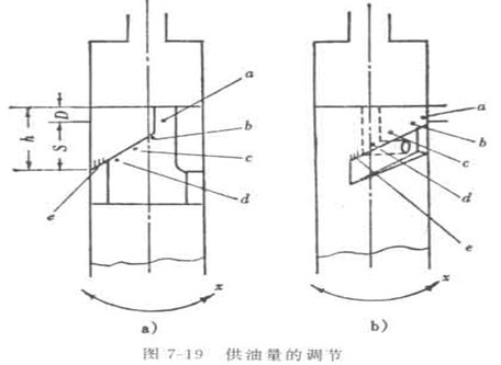
(3) the oil volume regulation
Plunger pair per cycle of oil quantity depends on the effective stroke of H3 size, whereby the plunger top face to the oil return hole of spiral groove or slot line distance, rotating the plunger can make the H change.
Theory on effective stroke: S=h-D ( oil inlet hole diameter )
5) of fuel injection pump plunger type composition and structure
Composition: pump, oil amount regulating mechanism, driving mechanism
(1) pump
Composition: plunger and plunger sleeve, a return spring, a spring seat, an oil valve, oil valve, oil valve springs, reducing container, oil outlet valve nut
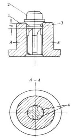
(1a ) oil outlet valve parts
Precision coupling: the oil outlet valve4and an oil outlet valve seat 1
The guide hole on the lower end, and a bore, through precision machining and matching grinding, after pairing cannot be interchanged
1) oil outlet valve structure
Oil outlet valve cone is the axial direction of the valve sealing cone valve, the tail in the guide hole of the sliding guide
Tail processing with slots, formed ten shaped section with a central vacuum ring:
2) out of the oil valve
A ) to prevent the fuel before the drop of oil, improve the injection speed
P >P >P residual – open pump spring
P >P >P residual – off pump spring
B. prevents after spraying drops of oil, improve the closing speed
The vacuum ring measures: pressure oil outlet valve to rise h, oil volume reductionπ d2h/4, stop feeding, decompression with a into the guide hole, the pump cavity outlet is cut off, but the oil outlet valve seat, because the oil outlet valve so that the pressure in the high pressure pipe volume decreased rapidly, off the oil quickly dry brittle
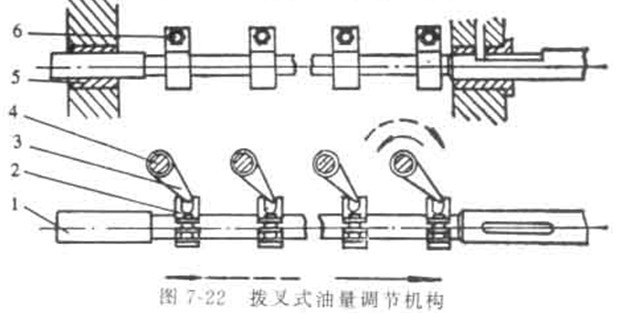
(2) an oil quantity regulating mechanism
(1a ) fork oil amount regulating mechanism
1 .regulates the cylinder oil quantity, ensure that the cylinder uniformity
2. regulation of single cylinder oil: a fixing bolt is loosened to change in the supply position of the shifting fork rod
(2a ) toothed bar type oil amount regulating mechanism
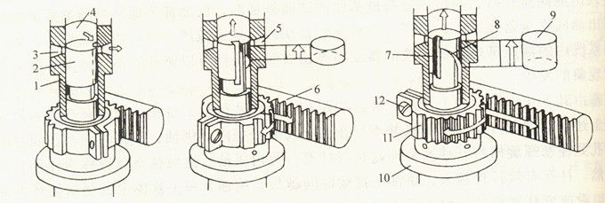
Structure: the lower end of the plunger cross convex block mounted on the transmission sleeve slot, a transmission sleeve sleeve in the plunger sleeve. Drive sleeve upper toothed fan, screw, gear and rack meshing fan
Regulation
Uniformity of the oil tank of regulation: through the rack pull – tooth fan to rotate drive sleeve to rotate through the cross bump – driven plunger rotation
Single cylinder oil supply quantity adjusting: loosen teeth fan fixing screw rotational drive sleeve – through the cross bump – driven plunger rotation – regulating cylinder oil
Note: in order to ensure the pump plunger and the pole position, the pump plunger drive sleeve, gear sector, toothed bar, the plunger has assembly mark, mark to align the assembly
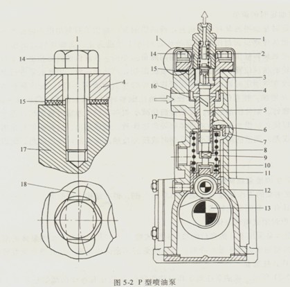
6) P type fuel injection pump
